+1 (312)439-2098
- Home
- Solutions
- Industrial
- Circuit with separate START and STOP buttons
Circuit with separate START and STOP buttons
In previous discussions, we covered safety mechanisms for preventing accidental device activation. Recently, we also explored how the duration of button presses can influence control logic. This article introduces refined circuit options that build on those ideas—some offering simpler, more elegant solutions.
Time Relay Circuit with Separate START and STOP Buttons
The circuit shown in Figure 1 resembles earlier examples, but with one key difference: the CRM-91H / 230V (or UNI) time relay is triggered not by the “S” input, but by powering the device itself. This eliminates the need for a separate control wire and allows for use of the same “a” function as the CRM-161.

The delay time “t” is typically set between 1.5 and 2 seconds—enough to distinguish between short and long presses. However, the delay can be extended depending on the application.
Operational sequence:
- If the START button is released before “t” elapses (a short press), power is cut and the output remains off.
- If the button is held for at least time “t”, the output activates and powers the load via terminal 18.
- The output also keeps the relay energized via a self-hold circuit through the closed STOP button.
- Pressing STOP breaks the hold circuit, switching off the consumer.
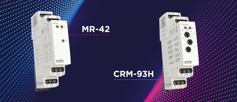
For applications requiring different voltages for control and output, the CRM-93H with 3x CO contacts can be used. This setup is shown in Figure 2.

Using the CRM-2T for Extended Timing
The CRM-2T relay—originally intended for star/delta motor switching—can also be adapted for this use. Channel 1 serves as the long-press timer with an adjustable range (up to 100 days), while channel 2 controls the consumer, even with a different voltage source.
Although not shown here, wiring diagrams are available in the downloadable documentation for the CRM-2T.
Single Button ON/OFF with Long Press Detection
In previous configurations, a separate STOP button was required. Figure 3 presents a circuit that enables both ON and OFF actions using long presses of a single button.

This solution incorporates the MR-41 pulse relay to maintain state. Each button press changes the state of the output, turning the consumer on or off. The MR-41 responds to the rising edge of the signal at the ON/OFF input. Once the delay ends and the time relay output activates, the pulse relay switches accordingly.
Long Press to Turn On, Short Press to Turn Off
Certain applications may require a long press to activate a device and a short press to deactivate it. Figure 4 shows a configuration for this functionality.

When the device is already running, a short press immediately switches it off. This is achieved by allowing the button’s signal to reach the ON/OFF input of the pulse relay only when the relay is active.
This setup uses the MR-42 pulse relay, which has two outputs. Terminals B1 and B2 are connected so both outputs operate together, similar to an MR-41 but with added functionality:
- One output controls the consumer.
- The other sends the pushbutton signal to the ON/OFF input.
Here’s how it works:
- A long press activates the time relay, which energizes the MR-42 and powers the load.
- While the button is still held, the ON/OFF input receives voltage from both the time relay (terminal 18) and the pushbutton itself.
- This prevents further activation until the button is released and pressed again.
- When the MR-42 is active and the button is pressed again (short press), the direct signal path triggers an immediate shutdown—no delay required.
This configuration ensures responsive short-press deactivation while avoiding false triggers during long presses.
Final Notes
The circuit diagrams referenced in this article are conceptual and may contain errors despite thorough testing. It is the responsibility of the installer to evaluate and adjust each design for the intended use case. Neither the author nor the company assumes liability for damage or malfunction resulting from these examples.
Please note that wire colors shown in illustrations are for clarity only and may not reflect industry-standard wiring conventions.
Didn't find what you were looking for?
Technical Support
+1 (312) 439-2098
techsupport@elkoepna.com
Customer Support
+1 (251) 284-6636
elkosupport@elkoepna.com
General Inquiries
+1 (608)746-1332
info@elkoepna.com
Company Headquarters
1150 NW 72nd Ave, Tower I,
Suite 455 #9226, Miami, FL 33126