+1 (312)439-2098
- Home
- Solutions
- Industrial
- Relay-Based Protection Against Accidental Switching
Relay-Based Protection Against Accidental Switching
Accidental activation or shutdown of machines and devices can have serious consequences—ranging from security concerns to equipment damage. Whether it’s in a workshop, industrial setting, or even a home environment, adding simple protections can significantly improve safety.
This guide presents practical circuit solutions to help prevent unintended activation or deactivation, with a focus on time and impulse relay configurations.
Preventing Accidental Switching with Impulse Relays
In industrial settings, one well-known safety method is the two-hand start system. This approach requires pressing two pushbuttons simultaneously—positioned far enough apart that one hand cannot reach both. The circuit itself is simple: the pushbuttons are connected in series, and pressing both provides the START signal.
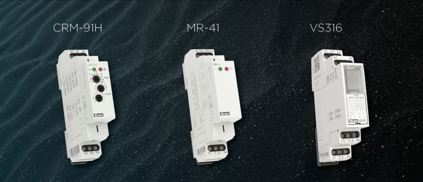
Another approach uses a double-press method to activate a pulse relay, such as the MR-41. In this setup (Figure 1), pressing the button once doesn’t activate the load. Only upon a second press—within a timed window—does the pulse relay toggle, switching the machine on or off depending on its prior state.

Here’s how it works:
- The first button press does not change the output.
- When released, the “S” input of the CRM-91H time relay (set to function “g”) treats this as the start signal.
- This begins a release delay and simultaneously energizes the relay output.
- Terminal 15 of the changeover contact receives the button signal. It is only routed to the ON/OFF input of the MR-41 pulse relay via terminal 18 during the timing window.
- If the second press occurs during this window, the pulse relay toggles its output.
This setup prevents unwanted switching due to accidental button presses. A second press is required within the delay period to change the machine’s state. If no second press follows, nothing happens—minimizing unintended operation. For critical machinery, an additional emergency stop function should be included (not shown in the diagram).
Power-Loss Recovery Protection Using an Auxiliary Relay
One drawback of the pulse relay approach is that after a power outage, the MR-41 returns to its previous state when power is restored. In some applications, this behavior is undesirable.
To address this, a standard auxiliary relay (e.g., VS316/230) can be used in a self-hold configuration instead. Figure 3 illustrates this variation.
Operation summary:
- The first button press (release) activates the CRM-91H, just as in the previous setup.
- During the timing window, a second button press activates the auxiliary relay.
- The relay’s contacts (21–24) maintain the self-hold condition and power the load.
- A separate STOP pushbutton can be used to break the hold and deactivate the machine.
This method ensures that after a power failure, the load does not automatically return to the previous state—offering a safer default behavior.
Final Notes
These circuits are conceptual examples intended to illustrate protective relay configurations. While tested under controlled conditions, they may require adaptation for real-world installations.
Important: Always verify the suitability of any circuit for your application. Follow all safety standards and regulations. Wire colors shown in diagrams are for clarity only and may not correspond to standard conventions.
Didn't find what you were looking for?
Headquarters
1150 NW 72nd Ave, Tower I,
Suite 455 #9226, Miami, FL 33126
Tech Support
+1 (312)439-2098
techsupport@elkoepna.com
General Contact
+1 (608)746-1332
info@elkoepna.com
Central Warehouse
7200 Intermodal Dr, Louisville, KY 40258