+1 (312)439-2098
- Home
- Solutions
- Industrial
- Timed Disconnection of High-Current Devices
Timed Disconnection of High-Current Devices
Controlling the operation of machines with precise timing is simple with the use of time relays—especially multifunction variants. These devices often integrate the most commonly used timing functions, allowing operators to rely on a single relay type for a range of tasks. This reduces errors and increases the likelihood of selecting the appropriate timing mode.
However, there are situations where installing a time relay directly is not practical. This may be due to limited physical space or the absence of dedicated control wiring. Still, if space is available—typically in a control cabinet—it is often possible to implement a remote solution. Even if a device is normally activated locally, it’s important to detect when it begins drawing current.
In such cases, current monitoring relays are especially useful. These devices monitor the power line and trigger a control signal as soon as the connected load begins to consume current. This signal can then activate a time relay to control downstream behavior.
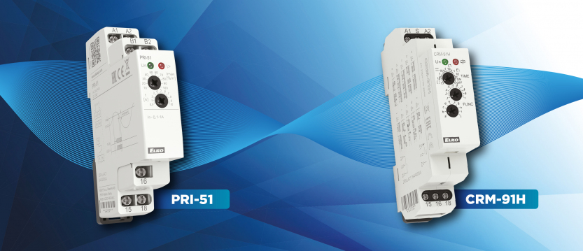
Using PRI-51/x Current Monitors
ELKO EP’s PRI-51/x series current limit switches are well-suited for this purpose. These monitors are available in a range of versions, each designed for different maximum current thresholds (denoted by “x”). When current exceeds the configured threshold, the internal relay activates.
To detect the operation of a high-consumption device, set the threshold below its normal operating current. This ensures that whenever the device is switched on, the current monitor will send an activation signal to the connected time relay.
Automatic Disconnection During Overload
Figure 1 illustrates a practical use case: limiting energy consumption by temporarily disconnecting high-current loads. This can help reduce costs or protect infrastructure from overload. The system monitors the load and disconnects the power if the consumption exceeds a set limit. After a delay, the system attempts to reconnect. If the overload persists, disconnection repeats.
This principle can also be used in community settings to prevent unauthorized high-load usage—for example, discouraging power theft in shared spaces. While this circuit focuses on functional logic, all relevant safety standards must be considered and implemented based on the installation environment.

The setup consists of two modules installed in a control cabinet. The consumer’s power line passes through the internal shunt of the PRI-51/x current monitor (B1–B2), then through contact 15 of the time relay and out through contact 16 to the load.
When the current exceeds the set threshold, the current monitor energizes and sends a signal (via terminal 18) to the “S” input of the CRM-91H time relay. Supplied with constant voltage, the CRM-91H is set to operate in release delay mode on the rising edge of the signal. Once triggered, the timer disconnects power to the consumer. As the monitored current drops to zero, the current relay resets. After the delay period ends, power is restored.
If the high current draw is still present, the shutdown cycle repeats until the high-consumption device is disconnected.

Timed Operation of High-Current Devices
In another application (Figure 2), the physical wiring remains the same, but the time relay is set to the “h” function—delayed pull-in and delayed release based on the control signal. Upon receiving the signal at input “S”, the relay waits for time “t” before energizing. When the signal ends, it again waits for time “t” before switching off.
This setup allows the device to remain powered for a specific duration, enabling timed operation from the supply side. This configuration is ideal for loads that should not be switched on and off rapidly, helping to prevent wear or damage due to frequent cycling.
Additional Notes
Both circuit variations allow the use of contact 16 from the current monitor to lock out additional circuits. This ensures priority for higher-consumption devices passing through the same shunt.
If the current consumption in the monitored circuit is below the set threshold, priority is not applied and multiple consumers can operate simultaneously.
Disclaimer
The example circuits presented here are conceptual and may contain errors despite repeated checks or workshop testing. It is the responsibility of the installer to verify suitability for the intended application and to make any necessary adjustments. Neither the author nor the company accepts liability for damage or other issues arising from use of these solutions. Wire colors in the diagrams are for illustrative purposes only and may not reflect standard wiring practices.
Didn't find what you were looking for?
Headquarters
1150 NW 72nd Ave, Tower I,
Suite 455 #9226, Miami, FL 33126
Tech Support
+1 (312)439-2098
techsupport@elkoepna.com
General Contact
+1 (608)746-1332
info@elkoepna.com
Central Warehouse
7200 Intermodal Dr, Louisville, KY 40258