+1 (312)439-2098
- Home
- Solutions
- Industrial
- Using Relays for Smart Light Signaling
Using Relays for Smart Light Signaling
Garage doors left open overnight can pose a risk—whether to vehicles, property, or personal safety. One way to prevent this is by enabling the delayed automatic closing function available in most motorized garage door systems. Although users sometimes leave it disabled for practical reasons, such as easier access during unloading, the function is easy to activate and typically includes advance warning before closing.
A common form of this warning is a connected external light. When the gate is open, the light turns on steadily, and before the gate closes, it begins to flash—alerting anyone nearby of the automatic movement. This straightforward signaling method isn’t limited to gate control; it’s also applicable in various operational contexts.
For example, in quiz games, a steady light can mark the start of a countdown, with a flashing signal indicating the time is nearly up. In the sections that follow, we’ll explore several light signaling solutions using relays—and later, triacs—ranging from simple configurations to more advanced, asymmetric timing setups.
ELKO EP Asymmetric Timers: An Overview
Several of ELKO EP’s multifunction time relays are pre-configured with flashing signal functions. In the simplest case, all that’s needed is to select the correct timing mode, and the output begins flashing.
While some digital time switches also include programmable flash functions, their timing range is often more limited (typically 1–99 seconds). Figure 1 illustrates ELKO EP relays in the RELAY product group that include this capability.

Most time relays begin timing when power is applied, if set to do so. In the case of SMR-type relays, all functions can also be triggered via a START signal, while the relay remains continuously powered.
Standard time relays typically offer only one time setting, meaning the on/off durations are symmetrical. Asymmetric timers, by contrast, allow separate configuration of the pulse (on-time) and pause (off-time). Timing diagrams for each model are available in the respective product manuals.
Light Signaling for Countdown Timing
In a quiz game setting, the time available to answer can be indicated through light signals, as shown in Figure 2. The countdown begins with a steady light. As the deadline approaches, the light begins flashing, signaling that a response is required.

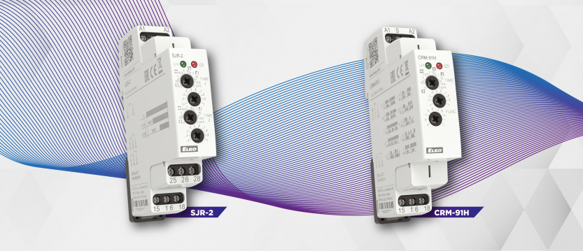
The setup is illustrated in Figure 3. Contact 16 of channel 1 on the SJR-2 relay maintains the steady light until time “t1” expires. At that point, the contact opens and power is transferred to terminal 25 of channel 2, which then supplies the CRM-91H relay. Configured to start on power-up, the CRM-91H begins flashing the indicator light for the remainder of the countdown (t2 − t1). Once the time ends, the circuit disconnects.

Asymmetric Flashing Configuration
To convert the flashing segment to an asymmetric pattern, replace the CRM-91H with a CRM-2H timer. This model allows independent configuration of the pulse and pause times, ranging from 0.1 seconds to 100 days. For example, the circuit can be set to have longer illumination intervals and shorter dark phases, or vice versa. Figure 4 includes both the wiring and timing diagrams for CRM-2H’s two modes: starting with a pulse or with a pause. For the latter, terminals A1 and S must be connected.

Dual-Speed Flashing
In some applications, such as competitive games or machine alerts, a more dynamic signal can improve visibility or urgency. Figure 5 shows a configuration where the initial steady light is replaced with a slower flashing signal. This makes the transition to the fast-flashing warning signal more noticeable. Figure 6 shows the corresponding timing diagram.


This variation uses an additional CRM-91H timer configured with a slower cycle to create the pre-warning phase. Its output is connected in parallel with the fast-flashing signal, and whichever is active controls the indicator light. For additional clarity, the outputs can also be wired to different color lights.
Reducing Wear: Silent Switching with Triacs
While relays are suitable for many flashing applications, they do have moving mechanical parts and generate noise. ELKO EP relays are highly durable, but for frequent or silent operation, solid-state alternatives are preferred.
The CRM-9S multifunction timer provides such a solution. Instead of a relay, it uses a triac, an electronic switching component that operates silently. It supports the same 10 timing functions as other CRM-9x series relays and is suitable for switching resistive (R) and inductive (L) loads up to 0.7 A. It is not recommended for capacitive (C) loads such as most 230 V LED lights unless marked compatible by the manufacturer.
Figure 7 shows a CRM-9S-based flashing circuit. The internal triac connects the supply input (A1) to the load, and its output runs in parallel with the SJR-2’s relay contact. An auxiliary relay is used to momentarily interrupt power to the CRM-9S during mechanical switching, preventing interference with the triac.

Note: Modifying the upper side of triac circuits can cause damaging voltage spikes. Use caution and follow standard safety practices.
Custom Asymmetric Flashing: Speed Shift
Figure 8 illustrates a more advanced setup using the CRM-2HE timer, which offers fine control via external potentiometers. One potentiometer sets the pulse time, while two different ones are used for the pause: one long, one short.

At the start, the circuit uses the longer pause setting, resulting in slower flashing. After “t1” of the SJR-2 expires, it switches to the shorter pause setting, speeding up the flashing rate. A CRM-91H relay determines the total active time and disconnects the module once time runs out.
To maintain consistent behavior, ensure that the total timing duration of the CRM-91H matches the “t2” duration set on the SJR-2.
Final Notes
The circuits in this article are presented as illustrative examples and may contain errors despite internal testing. Always verify circuit design and suitability for your specific use case. Installation and adjustments are the responsibility of the technician.
Neither the author nor the company accepts liability for damages or malfunctions arising from the use of these examples.
Didn't find what you were looking for?
Headquarters
1150 NW 72nd Ave, Tower I,
Suite 455 #9226, Miami, FL 33126
Tech Support
+1 (312)439-2098
techsupport@elkoepna.com
General Contact
+1 (608)746-1332
info@elkoepna.com
Central Warehouse
7200 Intermodal Dr, Louisville, KY 40258