+1 (312)439-2098
- Home
- Solutions
- Residential Buildings
- Bi-Directional Motor Control Using Relays
Bi-Directional Motor Control Using Relays

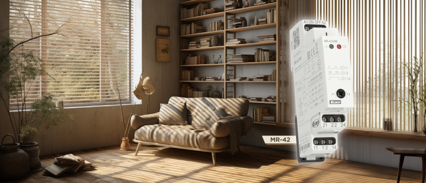
The MR-42 pulse relay from ELKO EP has proven its versatility in many applications beyond lighting control. In this article, we explore how to use it for bi-directional motor control, such as for blinds, gates, or garage doors.
Of course, we’re not just flipping switches—we’re aiming for smart, reliable functionality using compact, modular relay logic.
MR-42
The goal is to replicate the behavior of dedicated motor controllers using only one pushbutton (or multiple pushbuttons wired in parallel). The button should cycle through the following states:
- Press → move motor in one direction (e.g., UP)
- Press → stop
- Press → move motor in the other direction (e.g., DOWN)
- Press → stop
…and repeat.
The MR-42 pulse relay stores its state even after a power failure, maintaining the expected sequence.
Implementation with MR-42
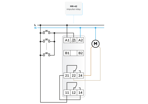
Figure 1 shows a basic wiring setup using a single MR-42:

| Relay 1 | Relay 2 | Motor action | |
|---|---|---|---|
| 1st press | ON | OFF | UP |
| 2nd press | OFF | ON | STOP |
| 3rd press | ON | ON | DOWN |
| 4th press | OFF | OFF | STOP |
This setup uses the step sequence of the MR-42 to control both direction and power:
- Channel 1 supplies voltage to the common terminal (21) of channel 2, which acts as a directional switch.
- Depending on the state of channel 2, the power is routed to one of the two motor windings.
This provides classic relay-based shutter or gate control—simple and effective. Note: This assumes the motor includes its own limit switches to stop motion at end positions.
Adding a Time Relay for Safety
Many factory motor controllers include a timer to cut power after a certain duration—even if the limit switch is not triggered. We can implement the same with a time relay.
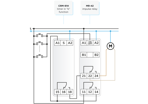
Figure 2 shows this expanded setup using the CRM-91H time relay in function “b” (release delay on supply voltage):
- Channel 1 of the MR-42 starts the CRM-91H.
- The time relay energizes and supplies power to terminal 21 (common).
- After the set delay, the CRM-91H deactivates, cutting power.

If desired, the CRM-161 time relay can be used as an alternative—it also supports function “b”, and can be configured the same way.
If different durations are needed for each direction (e.g., one direction is slower or gets stuck more often), two time relays can be used—each triggered separately via contacts 22 and 24. In this case, direct motor control happens through the outputs of both time relays, with the 11–21 connection enabling direction selection.
Obstacle Protection Using Current Monitoring
Factory controllers often include torque or obstruction detection, stopping or reversing movement if the gate hits an object. We can replicate basic protection using a current monitoring relay.
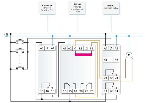
Figure 3 shows a configuration with the PRI-41 current monitor:
- The PRI-41 measures current via an internal shunt.
- Set the maximum current limit based on the motor’s normal operation range.
- If the current exceeds the limit and remains high beyond the configured delay, contacts 15–18 open, cutting power.

The PRI-41 supports both AC and DC, selectable via DIP switch. For motion control, the motor’s supply passes through contacts 15–18, then through the MR-42 direction relay, and finally to the motor.
To prevent the PRI-41 from reactivating prematurely during timing, activate its MEMORY function. This locks the relay in fault state until manually reset via the front panel button.
Limitations and Safety Considerations
While this setup provides basic obstacle protection, it lacks automatic reverse movement after detecting an obstruction—common in factory gate controllers. Implementing that would require additional relays and timing logic, at which point a microcontroller-based system becomes more practical.
Similar limitations apply to infrared barrier integration, although that’s easier to implement. For example, the IR barrier can trigger a relay that interrupts the closing direction’s supply line when an obstacle is detected.
Final Notes
The solutions in this article are based on conceptual circuit diagrams. While they have been tested under workshop conditions, they may require adaptation for real-world use.
Reminder: Wire colors in illustrations are for clarity only and may not match standard electrical codes.
Didn't find what you were looking for?
Technical Support
+1 (312) 439-2098
techsupport@elkoepna.com
Customer Support
+1 (251) 284-6636
elkosupport@elkoepna.com
General Inquiries
+1 (608)746-1332
info@elkoepna.com
Company Headquarters
1150 NW 72nd Ave, Tower I,
Suite 455 #9226, Miami, FL 33126