+1 (312)439-2098
- Home
- Solutions
- Residential Buildings
- Controlling a Hot Water Circulation Pump from Three Independent Switches
Control of three independent switches
In large buildings, offices, and even family homes, hot water is often needed in multiple rooms. When the hot water source is far from the taps, cold water must first be allowed to run before the hot water arrives—leading to unnecessary water waste.
Although water is still widely available in many regions, experts warn that access to clean water could become a serious global concern. Even today, excessive consumption impacts household costs. Efficient hot water circulation isn’t just practical—it’s economical and environmentally responsible.
In this article, we present two solutions for timed control of a circulation pump serving more than two hot water outlets. Both circuits use existing lighting switches to control pump timing and add a short delay before activation, avoiding unnecessary pump operation during brief visits to a room. The total runtime is set to ensure hot water reaches all outlets in the system.
Solution 1: Relay-Based Control from Three Locations
Figure 1 shows a circuit in which three independent light switches control lighting in separate rooms and simultaneously send a signal to the pump control logic.
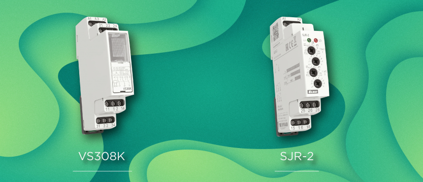
To ensure these switches do not interfere with each other’s lighting circuits, each switch operates an independent auxiliary relay. In this example, we used VS308K relays, though a 750L/230V with an ES-11 socket is also suitable.

When any switch is activated:
- Its corresponding auxiliary relay is energized.
- This disables the other two switches via its normally open contacts.
- Its normally closed contact supplies voltage to the SJR-2 time relay.
Although the SJR-2 is commonly used for timed load switching, here it manages both the activation delay and pump runtime.
How it works:
- Upon activation, both timers on the SJR-2 begin.
- Channel 1 (“t1”) sets the initial delay before the pump starts.
- If the lights are turned off during this time, the process is canceled.
- If the room remains occupied after “t1”, Channel 1’s relay energizes.
- Terminal 18 is connected to common contact 25 on Channel 2.
- When “t2” elapses, Channel 2 switches off the pump.
In effect, the pump runs for t2 – t1, allowing time for hot water to circulate, but only if the room remains occupied past the delay period
Solution 2: Diode-Based Logic OR for Simpler Wiring
While not widely used in standard installations, diodes can be an elegant solution for control logic. Typically used for rectification, diodes can also implement simple logic functions like OR connections—previously demonstrated in other articles.
This method became viable with the introduction of UNI-powered devices. But be cautious—not all products labeled “UNI” behave like ELKO EP’s UNI range.
A true UNI device operates reliably across 12–240 V AC/DC via the same two terminals. When connected through a diode on 230 VAC, only half of the AC sine wave reaches the input—so the device must support pulsating DC. We recommend the 1N4007 diode, rated at 1 A and 1000 V.
Figure 2 shows a circuit built on this principle.

The SJR-2/UNI time relay is powered via diodes connected to each switch, forming a logic OR. Any switch can trigger the process. If all lights are turned off during timing, the pump stops. If another room’s light is turned on mid-cycle, the timing continues or restarts.
- Anodes of the diodes are connected to the switches.
- Cathodes are joined at a common point feeding the SJR-2 input.
- This ensures one-way flow of control signals and avoids backfeeding.
- It also prevents LED flickering or unintended feedback into other circuits.
While mixed polarity diode connections are not recommended, consistent cathode orientation can be used as an alternative layout if needed.
Final Notes
These circuit examples are presented as conceptual solutions and should be tested and adapted for the specific application. Despite internal verification, wiring diagrams may contain errors.
Reminder: Wire colors shown in diagrams are for clarity only and may not reflect standard wiring conventions.
Didn't find what you were looking for?
Technical Support
+1 (312) 439-2098
techsupport@elkoepna.com
Customer Support
+1 (251) 284-6636
elkosupport@elkoepna.com
General Inquiries
+1 (608)746-1332
info@elkoepna.com
Company Headquarters
1150 NW 72nd Ave, Tower I,
Suite 455 #9226, Miami, FL 33126