+1 (312)439-2098
- Home
- Solutions
- Residential Buildings
- Monitoring Overcurrent and Undercurrent with PRI-32 and PRI-52 Relays
Monitoring Overcurrent and Undercurrent with PRI-32 and PRI-52 Relays
ELKO EP’s PRI-32 and PRI-52 current monitoring relays offer a compact and efficient way to monitor AC current—without the need for external shunt connections. Instead, they feature a built-in current transformer with a through-hole design: simply route the consumer’s power line directly through the device. No surprises—just straightforward, real-time current monitoring.
What Do These Relays Do?
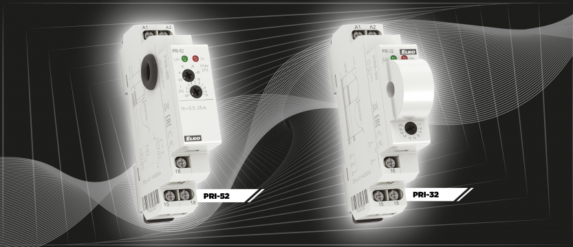
Figure 1 shows the PRI-32 and PRI-52 modules.

Figure 2 illustrates how these current monitors operate. Their behavior is similar to the PRI-51 “go/no-go” switch covered in a previous article:
- When the measured current exceeds the configured threshold, the relay activates (output contact closes).
- When current drops below the threshold, the relay deactivates via hysteresis.
The difference between the two lies in their response time:
- The PRI-32 reacts immediately—there’s no delay.
- The PRI-52 waits for the configured delay period before checking the current again. If the value is still over the threshold, the relay then activates. This helps filter out short disturbances and inrush currents.
The relays deactivate based on hysteresis:
- For PRI-32, hysteresis is 5% of the threshold.
- For PRI-52, it is fixed at 0.25 A.

Using an External Current Transformer
For loads that exceed the internal sensing limits of the relay, an external current transformer (CT) can be used. Accuracy will be affected by the CT’s specifications, but since these devices are meant for monitoring—not precision measurement—this is usually acceptable.
Important: When using a current transformer, never leave the secondary side open, as this can damage the transformer. If you implement priority switching using this method, blocking must be handled on the primary side.
Figure 3 illustrates how to wire the current monitor in conjunction with a CT.

Sequential Start-Up to Manage Load
In many installations, the main circuit breaker cannot handle the inrush current from several devices starting simultaneously—even if it can support their combined steady-state load.
In such cases, sequenced startup is a practical solution. We’ve previously discussed how to implement this using the SJR-2 time relay.
Practical Example: Summer Load Balancing
Consider a typical scenario during hot days: inverter-type air conditioners run continuously at high power. If the same 16 A breaker also supplies an electric oven, the combined startup or operating load may exceed the circuit’s capacity.
By using current monitoring relays in combination with time relays, you can stagger the startup of these devices—ensuring they don’t overload the system. This is especially helpful for installations where increasing the power supply would require a higher connection fee from the utility provider.
The Cost-Saving Angle
These solutions help avoid unnecessary upgrades to the electrical system, such as boosting the main breaker capacity or paying higher fixed charges for increased power limits. With minimal investment in relays, you can protect your infrastructure while improving efficiency.
Final Notes
The circuits and concepts described here are designed to provide inspiration for practical solutions. As always, installations must be checked and customized for their specific use case.
Reminder: The colors used in wiring diagrams are for clarity only and may not match industry-standard wiring conventions.
Didn't find what you were looking for?
Headquarters
1150 NW 72nd Ave, Tower I,
Suite 455 #9226, Miami, FL 33126
Tech Support
+1 (312)439-2098
techsupport@elkoepna.com
General Contact
+1 (608)746-1332
info@elkoepna.com
Central Warehouse
7200 Intermodal Dr, Louisville, KY 40258